Keys, Modules and Engine Controllers for 2023 Ram 3500
 1. Blank Key
  2. Blank Key
  3. Blank Key
  4. Screw
  5. Screw
  6. Steering Control Module
  7. Screw
  8. Steering Control Module
  9. Steering Control Module
  10. Door Module
  11. Heated Seat Module
  12. Heated Seat Module
  13. Occupant Restraint Control Cover
  14. Door Module, Left
  15. Door Module, Left
  16. Heated Seat Module
  17. Body Controller Module
  18. Engine Controller Module
  19. Occupant Restraint Control Cover
  20. Body Controller Module
  21. Camera Processor Module
  22. Vehicle Systems Interface Module
 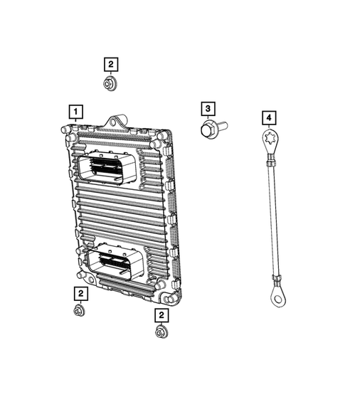 23. Engine Controller Module
  24. Engine Controller Module
  25. Air Bag Control Module
  26. Engine Controller Module
  27. Engine Controller Module
  28. Camera Processor Module
  29. Vehicle Systems Interface Module
  30. Body Controller Module
  31. Vehicle Systems Interface Module
  32. Engine Controller Module
  33. Park Assist Module
  34. Engine Control Unit Bracket
  35. Wireless Control Module Receiver
  36. Wireless Control Module Receiver
  37. Hex Flange Head Screw
  38. Park Assist Module
  39. Hex Flange Head Screw
  40. Hex Flange Head Screw
  41. Park Assist Module
  42. Engine Control Unit Bracket
  43. Alarm Module
  44. Gateway Module
  45. Camera Processor Module
  46. Gateway Module
  47. Push Pin
  48. Module Bracket
  49. Fd Ethernet Sgw Row Cybersecurity Gateway
  50. Gateway Module
  51. Nut And Washer
  52. Nut And Washer
  53. Gateway Module
  54. Nut And Washer
 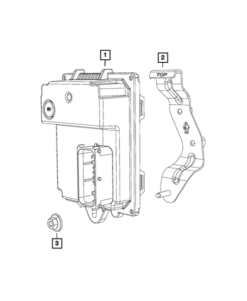 55. Controller Module
  56. Push Pin
  57. Push Pin
  58. Module Bracket
  59. Module Bracket
  60. Module Bracket
  61. Module Bracket
  62. Module Bracket
  63. Fd Ethernet Sgw Row Cybersecurity Gateway
  64. Module Bracket
  65. Transmission Control Module
  66. Module Bracket
  67. Anti-lock Brake System Module
  68. Anti-lock Brake System Module
  69. Forward Facing Camera Module
  70. Anti-lock Brake System Module
  71. Camera Processor Module
  72. Camera Processor Module
  73. Camera Processor Module
  74. Anti-lock Brake System Module
  75. Anti-lock Brake System Module
 No.
Part # / Description / Price
Price

 Mopar
Mopar 


5

MSRP $269.00
$177.10
5
MSRP $771.00
$501.40
6

Not For Sale
2 This part contains hazardous materials. Extra shipping costs apply.